


What Is Carbon Fiber Bike Layup Design?
Carbon fiber bike layup design is one of the most critical engineering stages in carbon frame development because it defines how the frame’s internal composite structure will carry load before manufacturing begins. At this stage, engineers plan the fiber orientation, carbon material selection, ply sequence, laminate thickness, reinforcement zones, overlap design, resin system, and layup schedule for each area of the frame, including the bottom bracket, head tube, downtube, chainstays, seatstays, fork crown, dropouts, brake mounts, and seatpost junction. Unlike metal frames, where tube material behaves more uniformly, carbon fiber is directional, meaning its strength and stiffness depend heavily on how each ply is positioned relative to the load path.
A professional layup design determines whether the final frame feels stiff, responsive, comfortable, durable, lightweight, or vibration-damping in real riding conditions. For example, specific fiber directions can improve bottom bracket power transfer, head tube torsional rigidity, rear-triangle compliance, impact resistance, and fatigue durability, while poor layup planning can create weak zones, excess weight, inconsistent stiffness, delamination risk, or unstable ride feel. This is why experienced carbon bike manufacturers treat layup design as a structural engineering process, not only a production step, using FEA analysis, ply books, fiber angle control, prototype testing, fatigue validation, and ride feedback to ensure the frame achieves the intended performance and manufacturing consistency.
Carbon layup vs carbon material
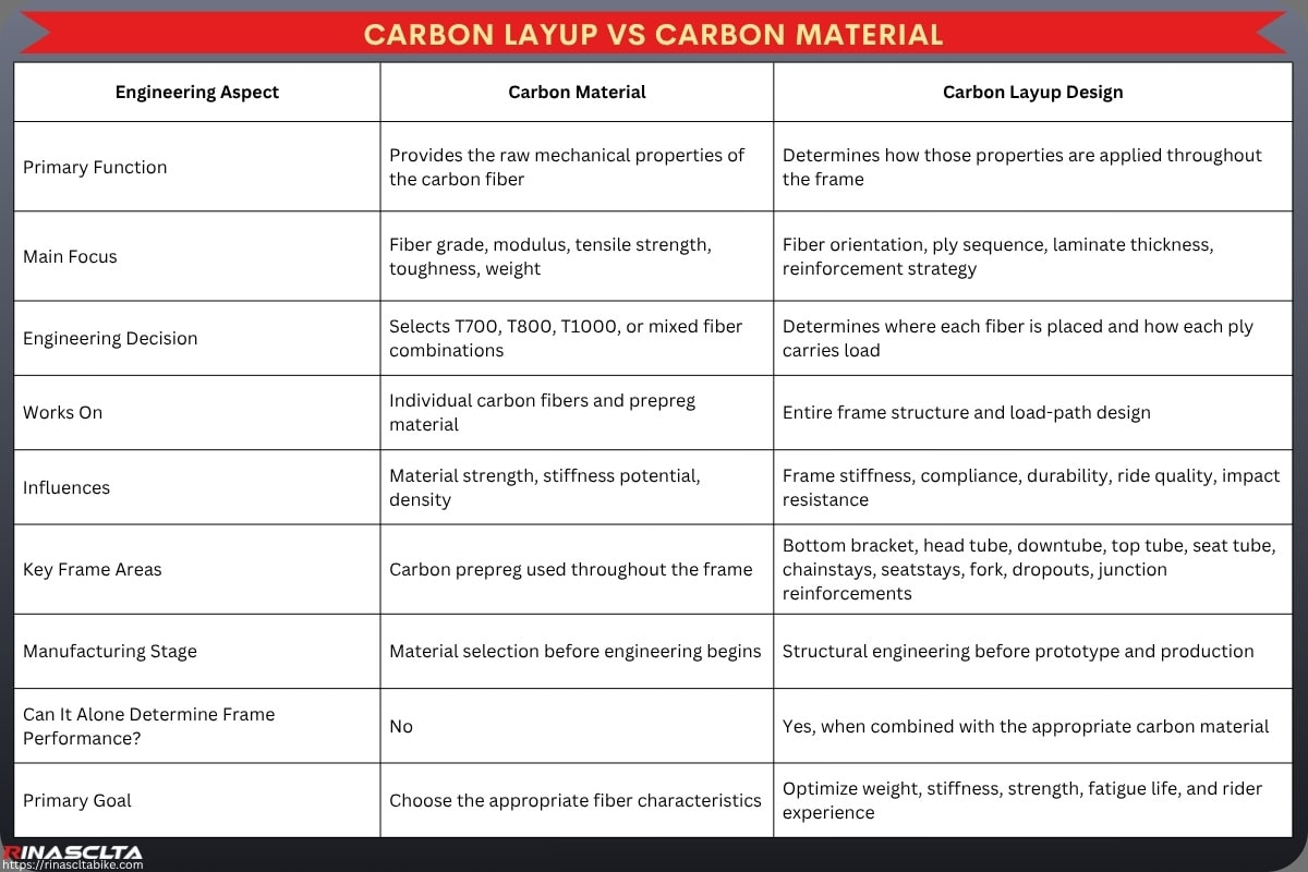
One of the biggest misconceptions in carbon bicycle manufacturing is that a higher carbon grade automatically produces a better frame. In reality, carbon material and carbon layup design serve different engineering purposes, and frame performance is determined by the combination of both rather than by fiber grade alone. Materials such as Toray T700, T800, T1000, or M-series fibers provide different tensile strength, tensile modulus, elongation, and weight characteristics, but these properties only describe the raw carbon fibers themselves. Without a properly engineered layup, even premium fibers can produce a frame that is too flexible, too harsh, excessively heavy, structurally weak, or prone to premature fatigue.
Carbon layup engineering determines where each carbon grade is used, how many plies are required, which fiber orientation is selected (0°, ±45°, 90°), how reinforcement is distributed, how loads travel through the frame, and how stiffness, compliance, impact resistance, and durability are balanced. Professional manufacturers often combine multiple carbon grades within a single frame, placing higher-modulus fibers in areas requiring maximum stiffness while using tougher fibers in high-impact or fatigue-critical zones. The result is a frame that achieves the desired ride quality, structural efficiency, manufacturing consistency, and long-term reliability, demonstrating that layup engineering—not carbon grade alone—is the primary factor that determines how a carbon bike performs
| Engineering Aspect | Carbon Material | Carbon Layup Design |
| Primary Function | Provides the raw mechanical properties of the carbon fiber | Determines how those properties are applied throughout the frame |
| Main Focus | Fiber grade, modulus, tensile strength, toughness, weight | Fiber orientation, ply sequence, laminate thickness, reinforcement strategy |
| Engineering Decision | Selects T700, T800, T1000, or mixed fiber combinations | Determines where each fiber is placed and how each ply carries load |
| Works On | Individual carbon fibers and prepreg material | Entire frame structure and load-path design |
| Influences | Material strength, stiffness potential, density | Frame stiffness, compliance, durability, ride quality, impact resistance |
| Key Frame Areas | Carbon prepreg used throughout the frame | Bottom bracket, head tube, downtube, top tube, seat tube, chainstays, seatstays, fork, dropouts, junction reinforcements |
| Manufacturing Stage | Material selection before engineering begins | Structural engineering before prototype and production |
| Can It Alone Determine Frame Performance? | No | Yes, when combined with the appropriate carbon material |
| Primary Goal | Choose the appropriate fiber characteristics | Optimize weight, stiffness, strength, fatigue life, and rider experience |

Why does every frame require a unique layup?
Every carbon bike frame requires a unique layup because every bicycle is designed to experience different loading conditions, rider inputs, terrain characteristics, and performance objectives. Although two frames may use the same carbon material and manufacturing process, their structural requirements are rarely identical. A road racing frame prioritizes power transfer, sprint stiffness, and low weight, while a gravel bike must balance compliance, impact resistance, and stability over rough surfaces. Similarly, a time trial frame focuses on aerodynamic efficiency and sustained high-speed stiffness, whereas a mountain bike frame must withstand large impacts, torsional loads, repeated fatigue cycles, and unpredictable terrain. For this reason, professional manufacturers develop a dedicated layup schedule for each platform rather than applying the same carbon laminate to every model.
Layup engineering is based on load-path analysis, rider weight distribution, tube geometry, riding discipline, expected impact loads, fatigue life, stiffness targets, vibration control, and manufacturing constraints. Engineers determine which carbon grades to use, where reinforcement is required, how many plies are needed, and which fiber orientations (0°, ±45°, 90°) best support each structural area. Even within the same frame family, different sizes may receive size-specific layup adjustments to maintain consistent stiffness and ride characteristics. This engineering approach ensures that every frame delivers the intended balance of weight, efficiency, durability, compliance, handling precision, and long-term reliability for its specific application.
| Bike Category | Primary Performance Goal | Structural Priority | Typical Layup Characteristics | Key Reinforcement Areas |
| Road Bike | Lightweight efficiency and power transfer | High stiffness with controlled compliance | High-modulus fibers around major load paths, optimized laminate for low weight and efficient power transfer | Bottom bracket, head tube, downtube, chainstays, seat tube junction |
| Gravel Bike | Comfort, stability, and mixed-terrain durability | Compliance with impact resistance | Balanced fiber orientations, additional toughness layers, vibration-damping laminate, reinforced impact zones | Seatstays, chainstays, fork blades, BB area, downtube, head tube |
| Time Trial (TT) | Aerodynamic efficiency and sustained high-speed performance | Aerodynamic stiffness and structural efficiency | High-stiffness laminate supporting aero tube sections, reinforcement for large tube profiles and integrated cockpit systems | Head tube, downtube, BB shell, seat mast, cockpit interface, fork crown |
| Mountain Bike (MTB) | Impact resistance, durability, and technical control | Maximum toughness and fatigue resistance | Multi-directional reinforcement, thicker laminate in high-load areas, additional impact-resistant plies | Head tube, downtube, BB shell, chainstays, suspension pivots (FS), rear triangle, dropouts |
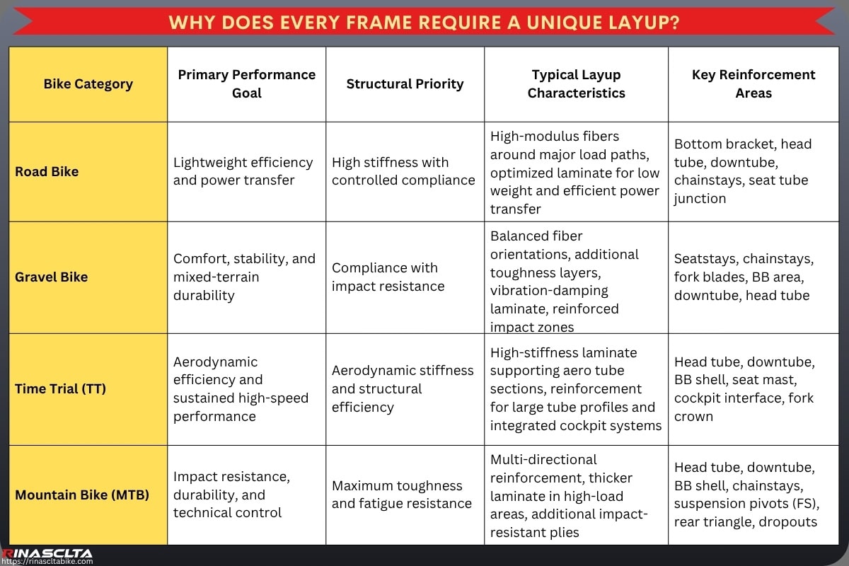
From a manufacturer’s perspective, the best carbon frame is not the one with the highest carbon grade or the fewest layers—it is the one whose layup is specifically engineered for its intended riding discipline. A category-specific layup allows each frame to achieve its own performance targets while maintaining structural integrity, manufacturing consistency, and long-term durability.
Core Principles of Carbon Bike Frame Layup Engineering
Carbon bike frame layup engineering is based on three core principles: fiber orientation, ply sequence and thickness, and reinforcement strategy. These principles define how carbon fibers carry load, how stiffness and compliance are distributed, and how the frame resists fatigue, impact, torsion, and rider-generated forces. Fiber orientation controls directional strength through 0°, 90°, +45°, and -45° layers; ply sequence and thickness control laminate behavior, wall thickness, stiffness-to-weight ratio, and vibration response; and reinforcement strategy strengthens critical zones such as the bottom bracket, head tube, downtube, chainstays, dropouts, fork crown, brake mounts, and seatpost interface. Together, these principles allow manufacturers to engineer a frame that meets specific targets for power transfer, steering precision, vertical compliance, impact resistance, fatigue durability, weight control, ride feel, and production consistency, making layup design the structural foundation of carbon bike performance rather than a simple material-stacking process.
Fiber orientation
Fiber orientation is the most fundamental principle of carbon bike frame layup engineering because carbon fiber is an anisotropic material, meaning it is extremely strong and stiff along the direction of the fibers but significantly less effective when loads are applied from other directions. Unlike aluminum or steel, which have relatively uniform mechanical properties, a carbon frame derives its structural behavior from the orientation of each carbon ply. By controlling fiber direction, engineers can precisely tune pedaling efficiency, steering precision, torsional rigidity, vertical compliance, fatigue resistance, and impact durability without significantly increasing frame weight.
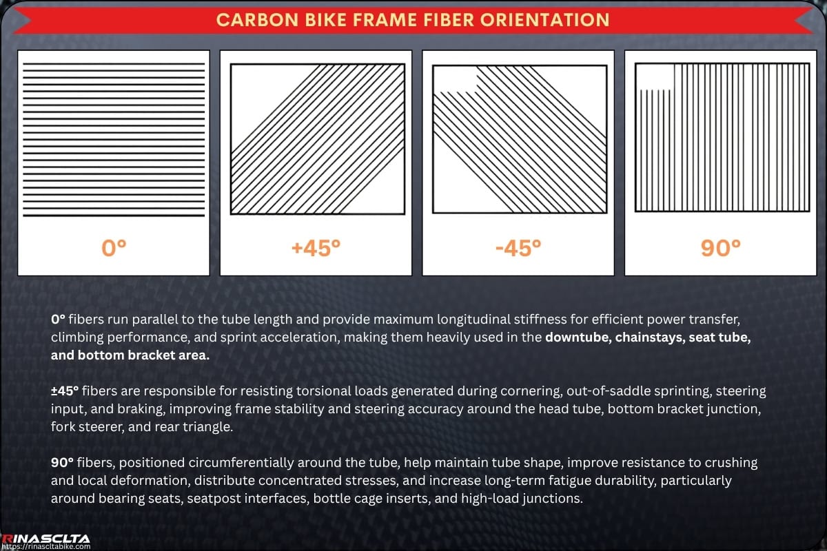
The most common fiber orientations are 0°, ±45°, and 90°, with each serving a different engineering purpose. 0° fibers run parallel to the tube length and provide maximum longitudinal stiffness for efficient power transfer, climbing performance, and sprint acceleration, making them heavily used in the downtube, chainstays, seat tube, and bottom bracket area. ±45° fibers are responsible for resisting torsional loads generated during cornering, out-of-saddle sprinting, steering input, and braking, improving frame stability and steering accuracy around the head tube, bottom bracket junction, fork steerer, and rear triangle. 90° fibers, positioned circumferentially around the tube, help maintain tube shape, improve resistance to crushing and local deformation, distribute concentrated stresses, and increase long-term fatigue durability, particularly around bearing seats, seatpost interfaces, bottle cage inserts, and high-load junctions.
Professional manufacturers rarely rely on a single fiber direction. Instead, they create a balanced laminate by combining multiple orientations within the same structural area, allowing the frame to manage complex multi-directional loads encountered during real riding. For example, the bottom bracket junction may contain a combination of 0° fibers for pedaling stiffness, ±45° fibers for torsional resistance, and 90° reinforcement for structural stability, creating an optimized stiffness-to-weight ratio while maintaining durability. The exact orientation and number of plies are determined through load-path analysis, finite element analysis (FEA), laboratory testing, and prototype validation, ensuring that each section of the frame performs according to its intended function.
Fiber orientation works together with different carbon fiber materials and weave structures to achieve the desired performance. Modern bicycle frames primarily use unidirectional (UD) prepreg carbon, where nearly all fibers run in a single direction, allowing engineers to precisely control stiffness, weight, and structural efficiency by adjusting the orientation of each individual ply. UD carbon is therefore the dominant structural material in high-performance frames because it provides the highest engineering flexibility and the best stiffness-to-weight ratio.
Other carbon fabrics are used for specific purposes. 3K woven carbon consists of woven bundles containing approximately 3,000 filaments per tow and provides excellent dimensional stability, impact tolerance, and surface appearance, although it generally adds more resin and weight than UD construction. Larger woven fabrics such as 6K or 12K are less common in premium bicycle frames and are typically used where additional toughness, cosmetic appearance, or manufacturing convenience is more important than minimizing weight. During production, these materials are supplied as raw prepreg carbon, where dry carbon fibers are pre-impregnated with a controlled amount of epoxy resin and stored under refrigerated conditions before layup. The combination of fiber grade (such as T700, T800, or T1000), prepreg quality, weave type, fiber orientation, and laminate design ultimately determines the frame’s stiffness, strength, compliance, fatigue life, manufacturing consistency, and overall ride performance.
Ply sequence and thickness
Ply sequence and thickness determine how the individual carbon layers work together as a single structural system. While fiber orientation defines the direction in which each layer carries load, the number of plies, stacking order, overlap location, and laminate thickness determine how the frame behaves under pedaling forces, steering loads, braking, impacts, vibration, and long-term fatigue. From a professional carbon bike manufacturer’s perspective, these parameters are carefully engineered to achieve the desired balance of weight, stiffness, strength, compliance, durability, and manufacturing consistency, rather than simply adding more carbon to make the frame stronger.
Engineers first identify the expected load paths throughout the frame using finite element analysis (FEA), structural calculations, laboratory testing, and ride-performance targets. Areas subjected to the highest stresses—such as the bottom bracket shell, head tube junction, downtube, chainstay bridge, fork crown, and rear dropouts—typically require additional plies or thicker laminates to withstand high pedaling torque, steering forces, braking loads, and repeated fatigue cycles. In contrast, lower-stress areas such as portions of the top tube, seatstays, and upper seat tube can often use fewer plies or thinner laminates to reduce overall frame weight while maintaining sufficient structural safety.
The ply sequence, or stacking order, is equally important because carbon layers interact differently depending on their position within the laminate. High-stiffness plies may be placed closer to the outer surfaces to improve bending resistance, while tougher or more compliant layers may be positioned internally to improve impact tolerance, crack resistance, energy absorption, and fatigue durability. Engineers also carefully manage ply overlap, transition zones, ply drop-offs, scarf joints, and reinforcement tapering to prevent abrupt stiffness changes or stress concentrations that could lead to delamination or premature failure. A well-designed stacking sequence allows loads to transfer smoothly between tubes and structural junctions, creating a frame that feels balanced and predictable under real riding conditions.
Laminate thickness is optimized according to the function of each frame section rather than being kept uniform throughout the bicycle. Increasing thickness generally improves stiffness and structural strength but also increases weight and may reduce ride comfort if overused. Reducing thickness lowers weight and can improve vertical compliance, but excessive reduction may compromise torsional rigidity, impact resistance, or fatigue life. Professional manufacturers therefore tune laminate thickness locally to match the intended performance characteristics of each frame category, whether it is an ultralight climbing bike, aero race bike, endurance platform, gravel frame, MTB, or e-bike.
Rather than maximizing the number of carbon layers, experienced manufacturers optimize the entire laminate architecture. By selecting the correct fiber orientation, ply sequence, laminate thickness, carbon grade, and reinforcement strategy, they create a frame that achieves the required stiffness-to-weight ratio, efficient power transfer, steering precision, vibration control, structural durability, and production repeatability while avoiding unnecessary material, excess weight, and manufacturing complexity.
Reinforcement strategy
Reinforcement strategy is the engineering process of strengthening only the areas of the frame that experience the highest mechanical loads instead of increasing carbon material uniformly across the entire structure. From a professional carbon bike manufacturer’s perspective, simply adding more carbon everywhere would produce a heavier frame without proportionally improving performance. Instead, engineers identify high-stress zones, load paths, stress concentrations, fatigue-critical areas, and impact-prone locations, then apply localized reinforcement where it provides the greatest structural benefit while keeping the rest of the frame as light and efficient as possible.
The reinforcement strategy begins with finite element analysis (FEA), laboratory testing, prototype evaluation, fatigue testing, and real-world ride feedback to understand how forces travel through the frame during pedaling, sprinting, climbing, braking, cornering, descending, and impact events. Areas such as the bottom bracket shell, head tube, downtube junction, chainstay bridge, fork crown, rear dropouts, brake mounts, seat tube junction, and suspension pivot locations (for full-suspension MTB) typically experience the highest stress concentrations and therefore require additional carbon plies, tougher fiber grades, optimized fiber orientations, or thicker laminate sections. Conversely, lower-load areas can maintain thinner laminates to reduce unnecessary weight.
Professional reinforcement is not simply a matter of adding more carbon; it is about placing the right material in the right direction. Engineers may introduce additional 0° fibers to improve pedaling stiffness around the bottom bracket, ±45° reinforcement to increase torsional rigidity around the head tube and steering system, or 90° plies to improve local bearing support, crush resistance, and dimensional stability around the headset, seatpost clamp, and bottom bracket interfaces. Reinforcement patches are also carefully shaped and tapered so that loads transition smoothly between adjacent laminates, preventing stress risers, abrupt stiffness changes, resin-rich zones, and delamination risks that could reduce long-term durability.
Modern carbon frames also use material-specific reinforcement strategies by combining different carbon grades within the same structure. Higher-modulus fibers may be placed in areas requiring maximum stiffness, while tougher intermediate-modulus fibers are used in regions exposed to repeated impacts or fatigue loading. In some cases, manufacturers also incorporate aramid fibers (such as Kevlar®) or other hybrid composite materials in selected impact zones to improve damage tolerance without significantly increasing weight. This multi-material approach allows each reinforcement area to be optimized for its specific structural function.
A well-engineered reinforcement strategy enables manufacturers to achieve an excellent stiffness-to-weight ratio, efficient power transfer, steering precision, impact resistance, fatigue durability, and long-term reliability without adding unnecessary material throughout the frame. Rather than making every section equally strong, professional layup engineering ensures that each section is appropriately strong for the loads it actually experiences, resulting in a lighter, more efficient, and better-performing carbon bicycle frame.
Carbon Fiber Frame Layup Design Across the Frame
A carbon bicycle frame does not use one uniform layup throughout its structure because different areas experience completely different loading conditions during riding. Forces generated by pedaling, steering, braking, cornering, impacts, rider weight, vibration, and road irregularities travel through the frame along different load paths, meaning each section requires its own structural solution. From a professional carbon bike manufacturer’s perspective, effective layup engineering is based on function-specific laminate design, where the fiber orientation, ply sequence, laminate thickness, reinforcement strategy, and carbon grade are optimized according to the mechanical demands of each frame area rather than applying the same construction everywhere.
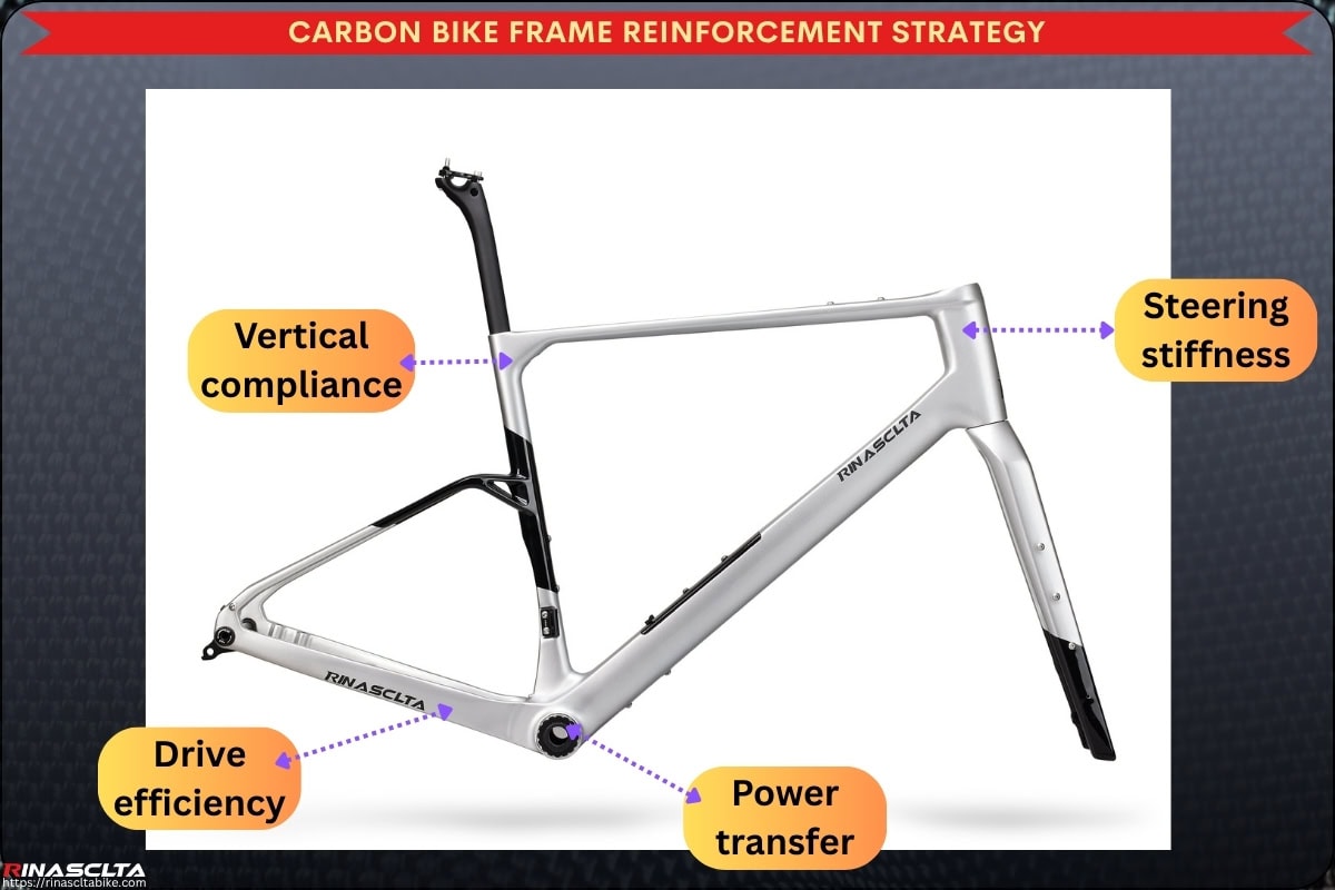
For example, the head tube and fork junction prioritize steering precision, torsional rigidity, and braking load resistance; the bottom bracket and chainstay area focus on power transfer, drivetrain efficiency, and fatigue strength under high pedaling torque; the top tube and seat stay area are engineered to balance structural integrity with vertical compliance and vibration damping for improved rider comfort; while the seat tube and seatpost junction must support rider weight, maintain saddle stability, distribute clamping forces, and control flex for long-distance comfort. By tailoring the layup to the specific function of each section, manufacturers achieve a frame with an optimized stiffness-to-weight ratio, balanced ride quality, structural durability, impact resistance, manufacturing efficiency, and long-term reliability, demonstrating that advanced carbon engineering is driven by localized structural design rather than a uniform laminate throughout the entire frame.
Head tube and fork junction
The head tube and fork junction are among the most highly stressed areas of a carbon bike frame because they must simultaneously withstand steering forces, front-wheel impacts, braking loads, torsional stress, and rider weight transfer. From a professional carbon bike manufacturer’s perspective, this region is engineered to maximize steering precision, front-end stiffness, structural durability, and bearing support while maintaining an efficient weight target. During hard cornering, sprinting, descending, and disc braking, large multi-directional forces travel from the fork through the headset into the head tube and surrounding frame structure, making this one of the most critical load-transfer zones in the entire bicycle.
To achieve these performance objectives, engineers use a carefully optimized layup with 0° fibers to increase longitudinal stiffness, ±45° fibers to resist torsional loads generated by steering and braking, and 90° reinforcement around the bearing seats to improve local compression strength, dimensional stability, and fatigue life. Additional reinforcement is typically applied around the head tube, fork crown interface, upper and lower headset bearings, downtube junction, and top tube junction, allowing loads to be distributed smoothly into the rest of the frame. The result is a front-end structure that delivers accurate steering response, confident high-speed handling, efficient braking performance, improved impact resistance, and long-term structural reliability without adding unnecessary weight.
Bottom bracket and chainstay area
The bottom bracket and chainstay area is the main power-transfer zone of a carbon bike frame because it connects the rider’s pedaling force to the drivetrain and rear wheel. During sprinting, climbing, and high-torque acceleration, large loads pass through the crankset, BB shell, downtube, seat tube, chainstays, rear dropouts, and rear axle interface, so this area must be engineered for drivetrain efficiency, lateral stiffness, torsional rigidity, fatigue resistance, and long-term bearing stability.
For layup design, engineers usually add stronger and more directional reinforcement around the BB shell, chainstay junction, downtube connection, seat tube base, and dropout load path. More 0° fibers help transfer pedaling force efficiently along the tube direction, while ±45° plies resist twisting from out-of-saddle efforts and chain torque. Local 90° reinforcement supports BB roundness, insert stability, bearing fit, and resistance to local deformation.
A well-designed bottom bracket and chainstay layup gives the bike a more direct and efficient ride feel, with better acceleration response, climbing stiffness, sprint stability, rear-wheel tracking, and drivetrain alignment. Poor layup in this area can create BB flex, power loss, creaking, bearing movement, chainstay fatigue, dropout misalignment, and inconsistent shifting, which is why professional manufacturers treat this zone as one of the highest-priority structural areas in carbon frame engineering.
Top tube and seat stay area
The top tube and seat stay area is engineered for rider comfort, vibration reduction, and structural balance because this part of the frame helps manage how road feedback travels from the rear wheel to the rider. Unlike the bottom bracket or head tube, where high stiffness is usually prioritized, the top tube and seat stays often need a more controlled layup that allows limited flex and vibration damping without reducing frame safety or handling precision.
In layup design, engineers may use thinner laminate sections, carefully controlled 0° fiber placement, balanced ±45° plies, and selected 90° reinforcement to maintain tube stability while allowing vertical compliance. The seat stays are especially important for absorbing high-frequency road vibration and rear-wheel impacts, while the top tube helps connect the front and rear triangle structurally without making the frame overly harsh. For endurance, gravel, and all-road bikes, this area may be tuned more toward comfort; for aero road and race frames, it must still maintain enough stiffness for responsive handling and frame integrity.
A well-designed top tube and seat stay layup improves long-distance comfort, rear-triangle compliance, vibration damping, traction, fatigue reduction, and overall ride balance. Poor layup in this area can make the bike feel too harsh, too flexible, unstable under load, or inconsistent between frame sizes, which is why professional manufacturers treat comfort zones as engineered structures rather than simply “soft” parts of the frame.
Seat tube and seatpost junction
The seat tube and seatpost junction is engineered to balance pedaling support, saddle load resistance, and vertical compliance because this area connects the rider’s seated weight, pedaling motion, and rear-triangle comfort behavior into one structural zone. It must support repeated loads from the saddle, seatpost, seat clamp, rider body weight, and pedaling forces, while also allowing controlled flex where appropriate to reduce road vibration and improve long-distance comfort.
In layup design, engineers reinforce the seat tube opening, seatpost insertion area, seat cluster, seatstay junction, and top tube connection to prevent cracking, ovalization, clamp damage, and laminate fatigue. 0° fibers help support vertical and longitudinal loads, ±45° plies improve torsional stability around the seat cluster, and 90° reinforcement improves local crush resistance around the seatpost and clamp area. For endurance, gravel, and all-road frames, the layup may be tuned to allow more controlled vertical compliance through the seatpost and rear triangle, while race frames usually prioritize firmer saddle support and efficient power transfer.
A well-designed seat tube and seatpost junction improves saddle stability, pedaling efficiency, rider comfort, vibration damping, seatpost clamping reliability, and long-term fatigue durability. Poor engineering in this area can lead to seatpost slipping, cracking around the clamp, harsh ride feel, excessive flex, creaking, uneven load transfer, or premature fatigue failure, which is why professional manufacturers treat this zone as both a structural support area and a comfort-tuning area.
Engineering Trade-offs in Carbon Bike Frame Layup Design
Carbon bike frame layup engineering is not about maximizing a single performance characteristic—it is about achieving the best balance between multiple competing engineering objectives. Every change to the laminate influences several aspects of the frame simultaneously. Adding more carbon layers may improve stiffness and impact resistance but also increases weight; reducing material may lower mass but decrease fatigue life or structural safety; increasing torsional rigidity may improve power transfer while reducing vertical compliance and rider comfort. From a professional carbon bike manufacturer’s perspective, successful layup development requires optimizing the relationship between fiber orientation, laminate thickness, carbon grade, reinforcement strategy, tube geometry, load paths, manufacturing feasibility, and ride characteristics rather than focusing on a single specification.
Professional engineers therefore develop each layup around the intended rider, bicycle category, performance targets, expected service life, manufacturing capability, and cost objectives. Through finite element analysis (FEA), prototype validation, fatigue testing, impact testing, laboratory measurement, and real-world rider feedback, they determine the optimal compromise between weight, stiffness, durability, comfort, production efficiency, and long-term reliability. The result is a frame that performs as a complete engineering system, where every structural decision supports the overall riding experience instead of maximizing one property at the expense of the others.
Weight vs durability
Weight vs durability is one of the most important trade-offs in carbon bike frame layup engineering because reducing frame weight is not simply a matter of removing carbon layers. Every ply contributes to the frame’s ability to resist pedaling loads, steering forces, braking stresses, impacts, fatigue cycles, and local stress concentrations. If too much material is removed or reinforcement is reduced excessively, the frame may become lighter but can also lose torsional rigidity, impact resistance, fatigue life, bearing support, and long-term structural reliability. From a professional carbon bike manufacturer’s perspective, the objective is not to build the lightest possible frame, but to build the lightest frame that safely meets its intended performance targets and durability requirements.
Achieving this balance requires careful structural optimization rather than simple material reduction. Engineers use finite element analysis (FEA), load-path analysis, ply optimization, localized reinforcement, fatigue testing, impact testing, and prototype validation to determine exactly where carbon can be removed and where additional reinforcement remains essential. Instead of applying a uniform laminate, carbon is distributed according to structural demand, allowing high-stress areas such as the bottom bracket, head tube, chainstays, fork crown, and dropouts to maintain sufficient strength while lower-load regions are optimized for weight reduction.
Modern layup engineering also combines different carbon grades, fiber orientations, laminate thicknesses, and reinforcement strategies to maximize the stiffness-to-weight ratio without sacrificing durability. High-modulus fibers may reduce the amount of material required for stiffness, while tougher intermediate-modulus fibers improve impact resistance and fatigue performance in critical areas. When executed correctly, this engineering approach produces a frame that is lightweight, structurally efficient, fatigue-resistant, impact-tolerant, and reliable throughout its service life, demonstrating that true performance comes from intelligent layup optimization rather than simply minimizing weight.
Stiffness vs comfort
Stiffness vs comfort is one of the most challenging aspects of carbon bike frame engineering because both characteristics are essential for ride performance, yet they often oppose each other. A frame with extremely high stiffness can maximize power transfer, steering precision, sprint response, and drivetrain efficiency, but it may also transmit more road vibration and impact forces to the rider, increasing fatigue during long rides. Conversely, a frame designed with excessive compliance may improve comfort but can reduce pedaling efficiency, steering accuracy, and handling confidence. From a professional carbon bike manufacturer’s perspective, the goal is not to maximize stiffness or softness, but to place stiffness only where it benefits performance while allowing controlled compliance where it enhances rider comfort.
Engineers achieve this balance through selective layup tuning rather than reducing stiffness throughout the entire frame. High-stiffness laminates with optimized 0° fiber orientation are concentrated around the bottom bracket, head tube, downtube, and chainstays to preserve efficient power transfer, steering accuracy, and torsional rigidity. At the same time, areas such as the seat stays, top tube, seat tube, and seatpost junction receive carefully engineered laminate thicknesses, fiber orientations, and reinforcement strategies that allow controlled vertical flex without compromising overall frame integrity. The objective is to isolate compliance primarily in the vertical direction while maintaining lateral and torsional stiffness where performance demands it.
Professional manufacturers further refine this balance using finite element analysis (FEA), vibration analysis, fatigue testing, laboratory stiffness measurements, and rider feedback. By optimizing fiber orientation, ply sequence, laminate thickness, tube cross-sections, and carbon grade combinations, engineers create frames that absorb road vibration, improve traction, reduce rider fatigue, and increase long-distance comfort while still delivering responsive acceleration, precise handling, and efficient power transmission. This targeted engineering approach allows modern carbon frames to combine race-level efficiency with endurance-level comfort, demonstrating that compliance is an engineered performance characteristic rather than simply reduced stiffness.
Manufacturing complexity vs performance
Manufacturing complexity vs performance is a key engineering trade-off because the highest-performing carbon frames often require significantly more sophisticated layup processes than standard production models. From a professional carbon bike manufacturer’s perspective, improving frame performance is not only about selecting better materials—it also involves increasing the precision of fiber orientation, ply sequence, localized reinforcement, carbon grade combinations, laminate transitions, resin control, and quality inspection. While these advanced engineering methods can produce lighter, stiffer, more durable, and better-riding frames, they also increase manufacturing time, labor requirements, tooling complexity, and production cost.
Advanced layup designs typically require a larger number of individually cut carbon plies, multiple prepreg materials with different mechanical properties, tighter placement tolerances, more complex EPS core designs, carefully controlled overlap and transition zones, and highly skilled technicians to position every layer accurately. Engineers may also specify size-specific layup schedules, localized reinforcement patches, asymmetric laminates, or hybrid combinations of T700, T800, and T1000 carbon fibers, each of which adds complexity to material management, layup sequencing, curing consistency, and quality control. As the number of unique plies increases, so does the possibility of placement errors, resin variation, fiber wrinkling, or dimensional inconsistency, requiring more rigorous inspection and process control.
Professional manufacturers therefore evaluate whether each engineering improvement provides meaningful performance benefits that justify its manufacturing impact. Through design optimization, prototype validation, laboratory testing, production trials, and cost-performance analysis, they determine where advanced layup techniques deliver measurable gains in stiffness-to-weight ratio, fatigue life, impact resistance, vibration control, and ride quality, while avoiding unnecessary complexity that offers little real-world advantage. The objective is to achieve the optimal balance between engineering performance, manufacturing efficiency, production consistency, scalability, and commercial viability, ensuring that the final carbon frame can be produced reliably while meeting its intended performance targets.
Carbon Bike Frame Layup Strategies for Different Bike Categories
Carbon bike frame layup strategies vary significantly across different bicycle categories because each type of bike is engineered to solve a different performance problem. While all carbon frames are designed using the same engineering principles of fiber orientation, ply sequence, laminate thickness, reinforcement strategy, and structural load-path optimization, the final layup philosophy is determined by the intended riding discipline, rider expectations, terrain, and loading conditions. A professional carbon bike manufacturer does not simply apply one universal laminate to every frame; instead, the layup is customized to achieve the ideal balance of stiffness, compliance, strength, impact resistance, fatigue durability, weight, handling precision, and ride quality for each application.
Performance targets directly influence where stiffness is concentrated, where compliance is introduced, and how reinforcement is distributed throughout the frame. For example, a road racing frame emphasizes maximum power transfer and steering precision, while an endurance platform prioritizes vibration damping and long-distance comfort. Gravel bikes require greater impact tolerance, vertical compliance, and stability for mixed terrain, whereas mountain bikes must withstand high-impact loads, repeated fatigue cycles, large torsional forces, and technical riding conditions. As a result, engineers modify fiber orientation, carbon grade selection, laminate thickness, reinforcement zones, and structural transitions according to the specific demands of each bicycle category, ensuring the finished frame delivers the intended riding characteristics without unnecessary weight or over-engineering.
| Bike Category | Primary Performance Target | Layup Philosophy | Engineering Priorities | Typical Reinforcement Areas |
| Road Racing Bikes | Maximum speed, power transfer, low weight | High stiffness-to-weight optimization with precise load-path control | Pedaling efficiency, torsional rigidity, steering precision, sprint response, aerodynamic efficiency | Bottom bracket, head tube, downtube, chainstays, fork steerer, headset junction |
| Endurance Road Bikes | Long-distance comfort with efficient performance | Balanced stiffness and controlled vertical compliance | Vibration damping, rider comfort, fatigue reduction, stable handling, sustained efficiency | Seat stays, seat tube, top tube, head tube, bottom bracket with tuned compliance |
| Gravel Bikes | Mixed-terrain durability and stability | Toughness-oriented laminate with increased compliance and impact resistance | Rough-surface control, traction, impact tolerance, fatigue life, wide tire compatibility | Fork blades, downtube, chainstays, seat stays, BB shell, head tube, dropout interfaces |
| Mountain Bikes | Technical control, impact resistance, structural durability | Maximum toughness with localized high-strength reinforcement | Impact absorption, torsional stiffness, fatigue resistance, suspension load management, obstacle durability | Head tube, downtube, bottom bracket, chainstays, seatstays, suspension pivots (FS), dropouts, fork crown |
From a manufacturer’s perspective, an effective layup strategy is not defined by using more carbon or higher-grade fibers, but by engineering the laminate to match the specific performance objectives of the bicycle category. This category-specific approach enables each frame to achieve its intended balance of efficiency, comfort, durability, handling, and long-term reliability while maintaining manufacturing consistency and structural optimization.
Road racing bikes
Road racing bikes are engineered with a layup philosophy that prioritizes stiffness and responsiveness because their primary objective is to maximize speed, power transfer, and handling precision under high-performance riding conditions. During sprinting, climbing, aggressive cornering, and rapid acceleration, the frame experiences significant pedaling torque, torsional loads, steering forces, and lateral bending, requiring the laminate to transfer rider input directly to the drivetrain and wheels with minimal energy loss. From a professional carbon bike manufacturer’s perspective, every carbon ply is positioned to improve the stiffness-to-weight ratio while maintaining sufficient strength and fatigue durability for competitive riding.
To achieve this, engineers concentrate high-stiffness laminates around the bottom bracket, downtube, head tube, chainstays, and fork steerer, using optimized 0° fibers for efficient power transfer, ±45° fibers for torsional rigidity and steering precision, and 90° reinforcement to maintain local structural stability around bearings and junctions. Higher-modulus carbon fibers may be selectively incorporated into these critical load paths to reduce weight while maintaining frame rigidity. Areas requiring controlled compliance, such as the seat stays or seatpost junction, are carefully tuned without compromising the frame’s race-oriented character.
The result is a frame that delivers instant acceleration, efficient power transmission, precise steering response, high-speed stability, and confident cornering, allowing riders to convert more of their effort into forward motion. Rather than making the entire frame uniformly rigid, professional layup engineering creates localized stiffness where performance demands it, ensuring the bike remains lightweight, structurally efficient, and responsive throughout competitive road riding.
Endurance road bikes
Endurance road bikes use a layup philosophy focused on greater compliance and rider comfort because the goal is to maintain efficiency over long distances without excessive rider fatigue. Instead of making the entire frame maximally stiff, engineers preserve strong bottom bracket stiffness, head tube rigidity, and drivetrain efficiency while tuning areas such as the seat stays, seat tube, top tube, fork blades, and seatpost junction for controlled vertical flex and vibration damping.
From a manufacturing perspective, this requires careful adjustment of fiber orientation, ply sequence, laminate thickness, and reinforcement transitions. More comfort-oriented layup does not mean weak or soft construction; it means the frame is designed to absorb high-frequency road vibration, reduce harshness, improve rear-triangle compliance, and maintain predictable handling during long rides. A well-engineered endurance layup delivers stable power transfer, smoother road feel, reduced muscle fatigue, better traction, and long-distance ride confidence, making it suitable for gran fondos, rough-road riding, all-day training, and performance-focused recreational cyclists.
Gravel bikes
Gravel bikes require a layup strategy that balances efficiency, durability, and vibration control because they must perform on both paved roads and rough mixed surfaces. The frame still needs sufficient bottom bracket stiffness, head tube rigidity, and chainstay support for efficient pedaling and stable handling, but it also needs stronger impact resistance, fatigue durability, rear-triangle compliance, fork-blade comfort, and downtube protection to handle gravel vibration, stone strikes, washboard roads, loose corners, and long-distance riding.
From a manufacturing perspective, gravel layup usually combines reinforced high-stress zones with compliance-tuned comfort zones. The bottom bracket, head tube, downtube, chainstays, fork crown, dropouts, and disc brake mounts receive additional reinforcement for load control and durability, while the seatstays, seat tube, top tube, and fork blades can be tuned for vibration damping and traction. A well-engineered gravel layup gives the bike efficient power transfer on road sections, stable control on rough terrain, improved rider comfort, and stronger long-term reliability under real mixed-surface use.
Mountain bikes
Mountain bikes use a layup philosophy centered on impact resistance and fatigue durability because they are exposed to the most demanding loading conditions of any bicycle category. During trail riding, enduro, downhill, and technical cross-country use, the frame must withstand large impact forces, repeated landing loads, rock strikes, torsional stress, braking loads, suspension forces, and millions of fatigue cycles. From a professional carbon bike manufacturer’s perspective, the objective is to build a frame that maintains structural integrity and precise handling under extreme conditions while avoiding unnecessary weight.
To achieve this, engineers apply extensive reinforcement around the head tube, downtube, bottom bracket shell, chainstays, seatstays, rear dropouts, brake mounts, and suspension pivot locations (for full-suspension frames). The layup typically combines 0° fibers for structural stiffness, ±45° fibers for high torsional resistance, and 90° reinforcement for local impact strength, bearing support, and dimensional stability. Additional laminate thickness, tougher intermediate-modulus carbon fibers, and carefully designed reinforcement transitions help distribute concentrated loads and reduce the risk of crack initiation or delamination during repeated heavy impacts.
A well-engineered MTB layup delivers high impact tolerance, excellent fatigue life, precise steering control, stable suspension performance, reliable power transfer, and long-term structural durability across demanding terrain. Rather than maximizing stiffness alone, professional manufacturers optimize the laminate to absorb unpredictable trail loads while maintaining rider confidence, handling accuracy, and consistent performance throughout the frame’s service life.
From Layup Design to Prototype Validation
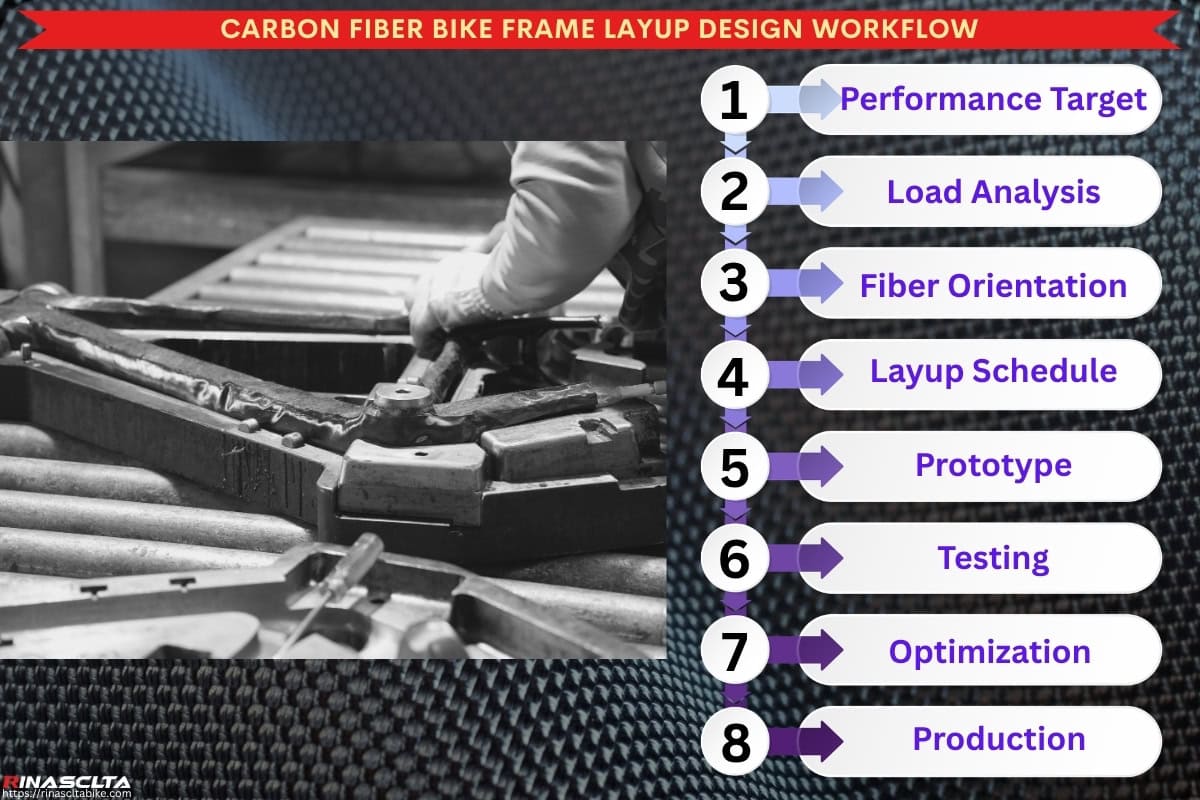
From layup design to prototype validation is the stage where the carbon frame’s structural concept is tested against real manufacturing and riding conditions before mass production begins. Engineers first create a digital layup plan, including the ply book, fiber orientation map, laminate thickness, reinforcement zones, carbon material selection, and cutting files, then use this plan to produce prototype frames through controlled prepreg cutting, manual layup, EPS molding, curing, demolding, alignment inspection, and initial QC. These prototypes are then evaluated through laboratory testing, fatigue testing, impact testing, stiffness measurement, assembly compatibility checks, and real ride feedback to confirm whether the frame meets targets for weight, stiffness, comfort, power transfer, vibration damping, impact resistance, fatigue durability, and handling precision. Based on the test results, engineers refine the ply sequence, reinforcement placement, fiber orientation, carbon grade selection, wall thickness, and local compliance zones, ensuring the final production layup is not only theoretically correct but also manufacturable, repeatable, safe, and consistent in real-world riding performance.
Digital layup planning
Digital layup planning is the engineering stage where the carbon frame structure is defined in CAD and technical documents before any prepreg is cut or placed into the mold. From a professional carbon bike manufacturer’s perspective, this stage converts performance targets into a controlled ply book, fiber orientation map, cutting file, layup schedule, reinforcement plan, laminate thickness strategy, material specification, and production SOP, so every frame section has a clear structural purpose before manufacturing begins. Engineers define where to use 0°, ±45°, and 90° plies, where to add localized reinforcement, where to reduce material for weight control, and how to manage overlap, ply drop-offs, tube transitions, and high-stress zones such as the head tube, bottom bracket, downtube, chainstays, dropouts, fork crown, and seatpost junction. Good digital layup planning improves stiffness-to-weight ratio, fatigue durability, impact resistance, ride-feel consistency, operator repeatability, material efficiency, and prototype success rate, while poor planning can lead to unnecessary weight, weak load paths, fiber wrinkles, inconsistent stiffness, failed testing, or costly layup revisions later.
Prototype frame production
Prototype frame production is the stage where the digital layup plan becomes the first real carbon frame sample for structural, assembly, and ride evaluation. From a professional carbon bike manufacturer’s perspective, this process uses the approved prepreg materials, cutting files, ply book, fiber orientation map, EPS/internal molding system, mold setup, curing cycle, and first-version QC checklist to build initial samples under controlled conditions. The purpose is not mass-production speed, but engineering verification: checking whether the layup is practical for operators, whether the laminate compacts correctly, whether the frame meets targets for weight, stiffness, alignment, surface quality, tire clearance, component fit, and structural consistency, and whether any issues such as wrinkles, voids, resin pooling, weak reinforcement, demolding damage, or assembly interference need to be corrected before final testing and production release.
Laboratory and ride testing
Laboratory and ride testing are used to validate whether the prototype frame meets both engineering targets and real riding expectations before the layup is approved for production. Laboratory testing measures objective performance such as bottom bracket stiffness, head tube torsional rigidity, frame alignment, fatigue durability, impact resistance, load deformation, and structural safety, often using static load fixtures, fatigue test rigs, impact machines, displacement sensors, strain gauges, and ISO-based test procedures. Ride testing then checks how those numbers translate into real-world behavior, including power transfer, steering precision, vibration damping, rear-triangle compliance, comfort, traction, braking stability, and rider confidence. Together, these tests confirm whether the layup delivers the intended balance of stiffness, durability, comfort, weight, and ride quality, while giving engineers the data needed to refine the frame before mass production.
Iterative refinement
Iterative refinement is the controlled adjustment stage where engineers modify the carbon layup schedule based on prototype production results, laboratory testing, ride feedback, and manufacturing observations before final production release. From a professional carbon bike manufacturer’s perspective, this may include changing fiber orientation, ply sequence, laminate thickness, carbon grade selection, overlap design, reinforcement size, ply drop-off position, or local compliance zones to improve frame weight, BB stiffness, head tube rigidity, vibration damping, impact resistance, fatigue life, and ride-feel consistency. This stage is valuable because small layup changes made before final tooling and mass production can prevent larger problems later, such as failed fatigue testing, excessive weight, harsh ride feel, weak reinforcement zones, inconsistent stiffness, production difficulty, or warranty risk, ensuring the approved layup is structurally reliable, manufacturable, repeatable, and aligned with the intended riding performance.
Custom Carbon Layup Development for OEM & ODM Projects
Custom carbon layup development is one of the highest-value engineering services an OEM/ODM carbon bike manufacturer can provide because it allows each frame to be optimized for a brand’s specific performance objectives instead of relying on a generic laminate. From a professional manufacturer’s perspective, carbon layup is not only a production process but a structural engineering solution that directly influences weight, stiffness, durability, comfort, impact resistance, fatigue life, ride quality, and manufacturing consistency. Depending on the project’s timeline, budget, and technical requirements, manufacturers can either adapt a proven layup platform or develop a completely new laminate architecture tailored to the customer’s geometry, riding category, and market positioning. Throughout the development process, engineers use load-path analysis, finite element analysis (FEA), digital layup planning, prototype manufacturing, laboratory testing, ride evaluation, and iterative refinement to ensure the final layup delivers the intended performance while remaining reliable and suitable for mass production.
Using existing layup platforms
Using existing layup platforms is an efficient OEM/ODM development approach that builds upon proven carbon engineering rather than creating an entirely new laminate from the beginning. From a professional carbon bike manufacturer’s perspective, these platforms are based on validated ply books, fiber orientation maps, reinforcement strategies, material specifications, prototype testing data, fatigue results, and mass-production experience, providing a reliable foundation for new projects. Instead of repeating the complete engineering cycle, manufacturers can adapt the existing layup to suit different frame sizes, paint schemes, component specifications, riding categories, or brand requirements, significantly reducing development time and technical risk.
Because the structural behavior of the platform has already been verified through laboratory testing, ride evaluation, production quality control, and field performance, brands benefit from faster product development, lower tooling investment, improved manufacturing consistency, and predictable ride characteristics. Where necessary, engineers can still make localized adjustments to fiber orientation, reinforcement zones, laminate thickness, or carbon grade combinations to fine-tune stiffness, weight, comfort, or durability while maintaining the reliability of the proven engineering platform. This approach is particularly valuable for ODM projects that require shorter lead times, lower development costs, and dependable production quality without compromising structural performance.
Developing custom layup schedules
Developing custom layup schedules means creating an application-specific carbon laminate structure based on the customer’s unique requirements for bike category, target rider, frame weight, stiffness profile, ride comfort, durability level, tire clearance, testing standard, and market positioning. Instead of using a standard ply book, engineers define a dedicated combination of fiber orientation, ply sequence, laminate thickness, carbon grade selection, reinforcement zones, overlap design, and size-specific tuning for the frame’s key areas, including the bottom bracket, head tube, downtube, chainstays, seatstays, fork crown, dropouts, brake mounts, and seatpost junction. This allows the manufacturer to create different performance characters for road racing, endurance, gravel, MTB, aero, or e-bike platforms while maintaining controlled stiffness-to-weight ratio, fatigue durability, impact resistance, vibration damping, ride feel, and production repeatability.
Performance validation before production
Performance validation before production is the final engineering verification stage that ensures the approved carbon layup performs in production exactly as it was designed during development. From a professional carbon bike manufacturer’s perspective, the objective is to confirm that the engineering targets for weight, stiffness, strength, durability, impact resistance, vibration control, and ride characteristics can be consistently achieved under real manufacturing conditions rather than only in CAD models or prototype samples.
This validation combines prototype inspection, laboratory stiffness testing, fatigue testing, impact testing, dimensional measurement, assembly verification, production trial runs, and ride evaluation to compare actual results with the original engineering specifications. Engineers also confirm frame weight tolerance, laminate consistency, fiber placement accuracy, curing quality, alignment, wall thickness, and critical component interfaces to ensure there are no deviations between the approved layup design and the production process. Only after these results consistently meet the defined performance targets is the layup released for mass production.
By validating both engineering performance and manufacturing repeatability, professional manufacturers ensure every production frame delivers the same power transfer, handling precision, rider comfort, structural reliability, fatigue life, and overall ride quality as the validated prototype. This process minimizes production variation, reduces warranty risk, improves quality consistency, and gives OEM and ODM customers confidence that the final product accurately reflects the original engineering objectives.
Conclusion
Carbon fiber layup design is far more than a manufacturing step—it is the structural engineering foundation that defines how a carbon bicycle frame performs throughout its entire service life. Every decision involving fiber orientation, ply sequence, laminate thickness, reinforcement strategy, and carbon material selection directly influences ride quality, power transfer, steering precision, vibration control, fatigue durability, impact resistance, manufacturing consistency, and overall frame weight. Whether developing a lightweight road racing frame, a compliant endurance platform, a durable gravel bike, or a high-impact mountain bike, the layup determines how the frame responds to real-world riding conditions long before production begins. For OEM and ODM projects, advanced carbon layup engineering also enables meaningful product differentiation, application-specific performance tuning, reliable mass production, and long-term quality assurance, making it one of the most valuable engineering capabilities in modern carbon bicycle development.