

Why Geometry Is the Foundation of Bike Performance?
Geometry is the foundation of bike performance because it determines the rider’s position, weight distribution, steering behavior, stability, and handling character before material selection, carbon layup, tube shape, or component specification can fully take effect. Key dimensions such as stack, reach, head tube angle, seat tube angle, wheelbase, chainstay length, bottom bracket drop, fork rake, trail, and front-center length define whether a bike feels aggressive, stable, comfortable, responsive, or confidence-inspiring in real riding conditions.
The same carbon frame material can feel completely different when the geometry changes. A low-stack, long-reach design with sharper steering will feel faster and more race-oriented, while a higher-stack, longer-wheelbase platform will feel more stable, comfortable, and endurance-focused, even if both frames use similar carbon fiber and manufacturing technology. This is why geometry development is one of the earliest and most important stages in OEM/ODM projects: it sets the engineering direction for rider fit, handling targets, tire clearance, cockpit design, carbon layup strategy, mold design, testing requirements, and final product positioning.
How Geometry Design Begins in Bike Development?
Geometry design begins long before CAD modeling or mold development. The first step is defining the target rider and intended use, because every bicycle category places different demands on rider position, handling characteristics, stability, comfort, and performance. A competitive road racing bike, endurance bike, gravel platform, MTB, or e-bike may all use carbon fiber construction, but each requires a different geometry philosophy based on factors such as terrain, riding duration, speed, tire size, rider posture, load requirements, and expected handling behavior. Establishing the intended application early helps manufacturers determine the appropriate direction for dimensions such as stack, reach, wheelbase, chainstay length, bottom bracket drop, head tube angle, and trail.
Once the target application is defined, engineers evaluate rider fit requirements, including rider height range, inseam length, torso-to-leg proportions, flexibility, riding style, and desired position on the bike. Proper fit is critical because geometry directly influences comfort, power transfer, weight distribution, aerodynamic efficiency, fatigue management, and long-term riding confidence. Manufacturers use this information to create the initial sizing strategy and determine how the geometry should scale across different frame sizes while maintaining consistent ride characteristics.
The final foundation of geometry development is establishing performance objectives. These objectives define how the bike should behave under real riding conditions, whether the goal is maximum aerodynamic efficiency, climbing performance, sprint stiffness, endurance comfort, gravel stability, technical handling, or all-around versatility. Engineers translate these targets into measurable geometry parameters that guide the entire development process, ensuring that the final frame delivers the intended balance of fit, handling precision, stability, comfort, responsiveness, and rider confidence before the project moves into detailed engineering and prototype development.
Target rider and intended use
Target rider and intended use are the starting points of geometry development because they determine how the bicycle should fit, handle, respond, and perform in real riding conditions. Before defining stack, reach, wheelbase, chainstay length, bottom bracket drop, head tube angle, fork rake, and trail, manufacturers must understand who the rider is, where the bike will be ridden, how long typical rides will be, what speed range is expected, and what balance between comfort, stability, responsiveness, efficiency, and load-carrying capability is required. A geometry that performs exceptionally well in a road race may feel unstable during multi-day bikepacking, while a bikepacking geometry may feel sluggish in a criterium race. This is why intended use is one of the first engineering decisions in any OEM/ODM frame project.
| Category | Primary Goal | Typical Rider Position | Handling Priority | Geometry Characteristics |
| Road Race | Maximum speed and efficiency | Aggressive, aerodynamic | Fast response and precise steering | Lower stack, longer reach, shorter wheelbase, steeper head tube angle, reduced trail |
| Endurance | Long-distance comfort and efficiency | Balanced, less aggressive | Stability and fatigue reduction | Higher stack, shorter reach, slightly longer wheelbase, stable steering geometry |
| Gravel | Mixed-surface versatility | Upright and adaptable | Predictable handling on varied terrain | Longer wheelbase, increased tire clearance, lower BB, higher trail, stable front-center |
| Bikepacking | Load carrying and multi-day riding | Comfortable for extended hours | Stability under cargo and rough terrain | Long wheelbase, longer chainstays, stable steering, lower center of gravity, accessory-focused geometry |
For manufacturers, selecting the correct rider profile and use case at the beginning ensures that all downstream decisions—including frame sizing strategy, carbon layup development, tire clearance, component compatibility, testing standards, and ride tuning targets—are aligned with the bike’s intended purpose. This allows the final production frame to deliver the expected ride characteristics rather than forcing geometry to compensate for an unclear product definition.
Rider fit requirements
Rider fit requirements are a critical part of geometry development because the same frame geometry will not suit every rider, even if they are the same height. Professional manufacturers evaluate factors such as body proportions, flexibility, riding posture, riding experience, and position preferences before defining geometry targets, because these characteristics directly influence stack, reach, top tube length, head tube length, seat tube angle, front-center distance, and overall rider balance on the bike. A well-designed geometry should allow the target rider to achieve an efficient, comfortable, and sustainable position without relying on excessive spacers, unusually long stems, or extreme component adjustments.
Different riders place different demands on the frame. Some prioritize aerodynamics and aggressive performance, while others require long-distance comfort, reduced back strain, or greater confidence on rough terrain. Understanding these requirements early helps manufacturers create a geometry platform that delivers better fit consistency, handling balance, power transfer efficiency, comfort, and rider confidence across the intended market segment.
| Rider Factor | Typical Characteristics | Geometry Influence | Engineering Consideration |
| Body Proportions | Long legs, short torso | Higher stack, shorter reach often preferred | Adjust fit balance and rider weight distribution |
| Body Proportions | Short legs, long torso | Lower stack, longer reach often preferred | Maintain efficient cockpit length and handling |
| Flexibility | High flexibility | More aggressive rider position possible | Lower stack, longer reach, reduced frontal area |
| Flexibility | Moderate flexibility | Balanced performance and comfort | Medium stack and reach targets |
| Flexibility | Limited flexibility | More upright riding position | Higher stack, shorter reach, reduced strain |
| Position Preference | Race-oriented | Aerodynamic and performance focused | Aggressive fit, efficient power transfer |
| Position Preference | Endurance-focused | Long-distance comfort | Relaxed posture, reduced fatigue |
| Position Preference | Adventure / Gravel | Stability and control on varied terrain | Upright fit, improved maneuverability |
| Position Preference | Bikepacking | Comfort under load and extended riding | Stable handling and sustainable riding posture |
By incorporating rider fit requirements into the geometry process, manufacturers can create frames that not only meet performance targets but also provide a more natural riding position, improved comfort, better handling behavior, and greater long-term rider satisfaction.
Performance objectives
Performance objectives are the engineering targets that define how a bicycle should behave on the road, gravel, trail, or during competition. Before geometry values are created, manufacturers must decide whether the priority is speed, comfort, stability, control, or a balanced combination of all four, because each objective influences key dimensions such as stack, reach, wheelbase, head tube angle, chainstay length, bottom bracket drop, fork rake, and trail. Geometry is ultimately a tool used to achieve a specific riding experience, and different performance goals often require different compromises. For example, a geometry optimized for maximum speed may sacrifice some comfort, while a geometry focused on stability may feel less agile during aggressive racing.
Professional manufacturers use these objectives to establish the design direction before moving into 2D geometry development, ensuring the final frame delivers the intended rider experience rather than simply meeting dimensional targets.
| Performance Objective | Primary Goal | Typical Geometry Direction | Riding Characteristics |
| Speed | Maximize efficiency and aerodynamic performance | Lower stack, longer reach, shorter wheelbase, steeper steering geometry | Fast acceleration, responsive handling, aggressive rider position |
| Comfort | Reduce rider fatigue during long rides | Higher stack, shorter reach, slightly longer wheelbase | Relaxed posture, improved vibration management, sustainable riding position |
| Stability | Improve confidence at high speed and rough terrain | Longer wheelbase, increased front-center, higher trail | Predictable steering, stable descending, improved traction |
| Control | Maximize rider confidence and precision | Balanced reach, optimized trail, controlled weight distribution | Accurate cornering, consistent steering response, improved technical handling |
In modern carbon bike development, the most successful geometry platforms are rarely designed around a single objective. Instead, manufacturers carefully balance speed, comfort, stability, and control according to the intended rider and application, creating a geometry package that delivers the desired performance characteristics while maintaining fit quality, handling consistency, and real-world usability.
Key Geometry Parameters and Their Influence
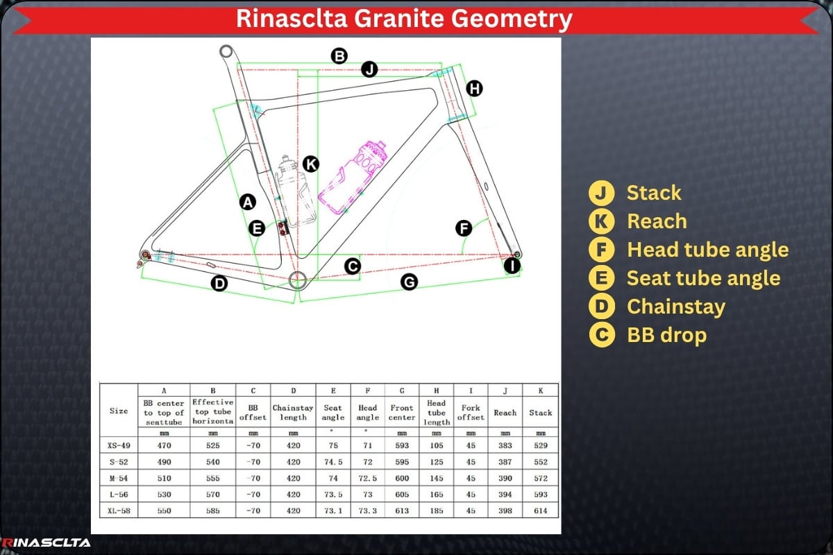
Key geometry parameters such as stack and reach, head tube angle and trail, wheelbase and chainstay length, and bottom bracket drop define how a carbon bike fits, steers, balances, and performs before the frame even reaches layup or material tuning. Stack and reach determine rider posture, cockpit length, aerodynamic position, and long-distance comfort; head tube angle and trail control steering speed, front-end stability, and cornering confidence; wheelbase and chainstay length influence straight-line stability, acceleration response, traction, and rear-end behavior; and bottom bracket drop affects center of gravity, cornering stability, pedal clearance, and overall handling balance. For a professional carbon bike manufacturer, these parameters are not isolated numbers but an integrated geometry system that must match the target rider, tire size, fork offset, riding category, component standards, and performance goals, because small changes can shift the frame from race-aggressive to endurance-stable, gravel-confident, or load-carrying adventure-focused.

Stack and reach
Stack and reach define the basic fit philosophy of a bike because they show where the rider’s handlebar position starts relative to the bottom bracket before stem, spacers, and handlebar shape are added. Stack controls front-end height and comfort, while reach controls cockpit length and rider extension; a low-stack, long-reach frame creates an aggressive aerodynamic race position, while a higher-stack, shorter-reach frame creates a more upright, stable, and endurance-friendly riding position. For manufacturers, stack and reach are more reliable than only seat tube length or top tube length because they help design consistent fit across frame sizes, reduce sizing confusion, and ensure the final bike matches the intended rider category, whether it is road race, endurance, gravel, or bikepacking.
Stack is the vertical distance from the bottom bracket center to the top-center of the head tube, and it defines the bike’s front-end height and rider posture. A higher stack gives the rider a more upright position, reducing pressure on the neck, shoulders, lower back, and hands, which is useful for endurance, gravel, bikepacking, and comfort-focused geometry; a lower stack creates a lower torso angle and smaller frontal area, improving aerodynamic efficiency and race positioning for road and aero bikes.
Reach is the horizontal distance from the bottom bracket center to the top-center of the head tube, and it defines the frame’s cockpit length before adding stem and handlebar dimensions. A longer reach stretches the rider forward for a more aggressive, stable, and performance-oriented position, while a shorter reach creates a more compact fit that improves comfort, handling confidence, and long-distance control; for manufacturers, reach must be balanced with stack, stem length, head tube angle, and frame size grading to keep fit consistent across the full size range.
Head tube angle and trail
Head tube angle and trail are the two most important geometry values controlling steering behavior because they define how the front wheel sits under the rider and how strongly the bike self-centers after steering input. Together, they influence whether a bike feels quick, sharp, stable, calm, nervous, or confidence-inspiring during cornering, descending, sprinting, braking, and rough-surface riding. A steeper head tube angle with lower trail usually creates faster steering and a more race-oriented response, while a slacker head tube angle with higher trail creates calmer steering, stronger stability, and better control on rough terrain or long descents.
Head tube angle is the angle of the steering axis relative to the ground, and it directly affects how quickly the front wheel reacts to handlebar input. A steeper head tube angle, common on aggressive road race bikes, makes steering feel faster, more direct, and more responsive, which helps in sprinting, criterium racing, and tight cornering; a slacker head tube angle, common on endurance, gravel, MTB, and bikepacking platforms, slows down the steering response and improves stability, especially at speed, under braking, or on loose surfaces.
Trail is the distance between where the steering axis meets the ground and where the front tire contacts the ground, and it strongly affects self-centering and front-end stability. More trail makes the bike feel more stable, predictable, and planted because the front wheel naturally wants to track straight, while less trail makes the bike feel quicker and easier to turn but potentially more nervous at high speed. For manufacturers, trail must be designed together with head tube angle, fork rake, wheel size, tire width, front-center length, and rider weight distribution, because changing one value can completely alter the steering character of the final production frame.
Wheelbase and chainstay length
Wheelbase and chainstay length control the balance between stability and agility because they define how far apart the wheels are and how close the rear wheel sits to the rider’s power center. A longer geometry generally feels more stable, planted, and confidence-inspiring at speed, while a shorter geometry feels quicker, more responsive, and easier to change direction; for manufacturers, these values must match the bike category, tire clearance, rider position, drivetrain layout, and handling target.
Wheelbase is the distance between the front and rear wheel axles, and it has a major influence on straight-line stability, descending confidence, and cornering behavior. A longer wheelbase gives the bike a larger contact footprint, making it feel calmer at high speed and more predictable on rough roads, gravel, or loaded bikepacking setups; a shorter wheelbase makes the bike feel more agile and reactive, which is useful for race bikes, criterium riding, and quick acceleration.
Chainstay length is the distance from the bottom bracket to the rear axle, and it mainly affects rear-end responsiveness, traction, and weight distribution. Shorter chainstays bring the rear wheel closer to the rider, creating a snappier acceleration feel and faster cornering response, while longer chainstays improve rear-wheel stability, climbing traction, tire clearance, and loaded-bike control; this is why road race bikes often use shorter stays, while gravel, endurance, and bikepacking frames usually benefit from slightly longer rear-center geometry.
Bottom bracket drop
Bottom bracket drop is the vertical distance between the wheel axle line and the center of the bottom bracket, and it directly affects the bike’s center of gravity, cornering stability, pedal clearance, and overall handling balance. A larger bottom bracket drop places the rider’s mass lower between the wheels, making the bike feel more planted, stable, and confidence-inspiring during cornering, descending, and long-distance riding; this is common on endurance road, gravel, and all-road frames where stability and control matter. A smaller bottom bracket drop raises the bottom bracket, improving pedal clearance and reducing pedal-strike risk, which is more useful for MTB, cyclocross, technical gravel, or aggressive riding where the bike must clear obstacles, ruts, and uneven terrain.
For manufacturers, bottom bracket drop must be designed together with wheel size, tire volume, crank length, terrain type, rider position, chainstay length, wheelbase, and intended handling target. Too much drop can make the bike feel stable but may increase pedal-strike risk with long cranks or low tire pressure, while too little drop can improve clearance but may raise the center of gravity and make the bike feel taller, less planted, or more nervous in corners. In carbon frame geometry development, BB drop is therefore not just a dimension on the drawing; it is a key handling parameter that helps balance cornering confidence, ground clearance, traction, rider stability, and category-specific ride feel.
How Geometry Changes Ride Characteristics?
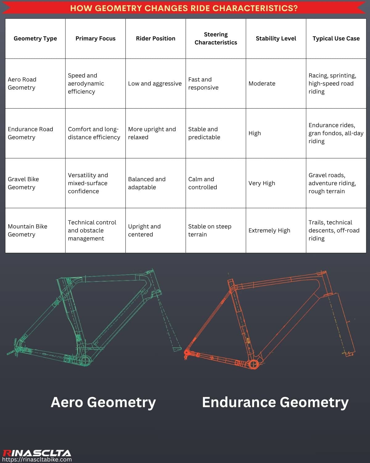
Geometry changes ride characteristics because it determines how the rider is positioned on the bike and how the bicycle responds to steering input, acceleration, braking, climbing, descending, and cornering. Even when two bikes use the same carbon material, wheel size, and component specification, differences in stack, reach, wheelbase, chainstay length, head tube angle, trail, bottom bracket drop, and front-center length can create completely different riding experiences. Professional manufacturers use geometry to define the bike’s intended personality, whether that is maximum speed, long-distance comfort, off-road stability, technical control, or all-around versatility. This is why geometry development is one of the most influential stages of bicycle engineering, as it establishes the foundation for fit, handling, confidence, efficiency, and overall ride performance.
| Geometry Type | Primary Focus | Rider Position | Steering Characteristics | Stability Level | Typical Use Case |
| Aero Road Geometry | Speed and aerodynamic efficiency | Low and aggressive | Fast and responsive | Moderate | Racing, sprinting, high-speed road riding |
| Endurance Road Geometry | Comfort and long-distance efficiency | More upright and relaxed | Stable and predictable | High | Endurance rides, gran fondos, all-day riding |
| Gravel Bike Geometry | Versatility and mixed-surface confidence | Balanced and adaptable | Calm and controlled | Very High | Gravel roads, adventure riding, rough terrain |
| Mountain Bike Geometry | Technical control and obstacle management | Upright and centered | Stable on steep terrain | Extremely High | Trails, technical descents, off-road riding |

Aero road geometry
Aero road geometry is designed to feel aggressive and responsive because its main purpose is to reduce aerodynamic drag, keep the rider in a powerful low position, and make the bike react quickly during sprinting, cornering, and high-speed racing. This usually means lower stack, longer reach, shorter head tube, steeper head tube angle, shorter wheelbase, shorter chainstays, lower frontal area, and race-focused cockpit positioning, all of which place the rider forward and lower over the bike for better speed efficiency and sharper handling.
Aggressive means the geometry pushes the rider into a lower, longer, more aerodynamic posture, reducing the body’s frontal area and improving high-speed efficiency. For manufacturers, this requires careful control of stack, reach, head tube length, seat tube angle, cockpit integration, and weight distribution, because an aero bike must feel fast without becoming uncomfortable, unstable, or too demanding for the target rider.
Responsive means the bike reacts quickly to rider input, especially during acceleration, sprinting, out-of-saddle climbing, and fast cornering. This comes from geometry choices such as shorter wheelbase, shorter chainstay length, steeper steering geometry, controlled trail, high bottom bracket and head tube stiffness, and efficient front-center balance, giving the bike a direct race feel while still requiring enough stability for descending, braking, and high-speed control.
Endurance road geometry
Endurance road geometry is designed around comfort and long-distance riding because its main purpose is to help riders maintain efficiency, control, and stable body position over many hours rather than forcing a purely aggressive race posture. This usually means higher stack, shorter reach, taller head tube, slightly longer wheelbase, more stable trail, wider tire clearance, and a more balanced rider weight distribution, giving the bike a smoother, calmer, and less fatiguing ride character.
Comfort comes from positioning the rider in a less stretched and less compressed posture, reducing pressure on the neck, shoulders, wrists, lower back, and hands. For manufacturers, this requires careful control of stack, reach, head tube length, seat tube angle, cockpit fit, tire clearance, and compliance compatibility, so the frame feels relaxed without becoming slow or disconnected.
Long-distance riding requires geometry that remains predictable when the rider becomes tired, the road surface becomes rough, or the ride extends for several hours. A slightly longer wheelbase, calmer steering behavior, stable front-center, and wider tire compatibility help improve descending confidence, vibration management, traction, and fatigue reduction, making endurance geometry suitable for sportive rides, gran fondos, rough-road training, and all-day performance cycling.
Gravel bike geometry
Gravel bike geometry is designed around stability and confidence because gravel riders deal with loose surfaces, changing traction, rough roads, descents, washboard vibration, and longer riding distances than typical road racing conditions. This usually means longer wheelbase, longer front-center, slightly slacker head tube angle, higher trail, lower bottom bracket, wider tire clearance, and a more upright rider position, giving the bike a calmer and more predictable feel when the surface is unstable or the rider is fatigued.
Stability comes from keeping the bike planted and predictable at speed, especially on rough gravel, broken pavement, and loose corners. Manufacturers use geometry values such as longer wheelbase, increased trail, lower center of gravity, and balanced weight distribution to reduce nervous steering and improve traction.
Confidence comes from making the bike easier to control when terrain changes suddenly. A gravel frame should allow the rider to descend, corner, brake, and climb on loose surfaces without feeling twitchy, which is why geometry must work together with wide tire clearance, lower tire pressure, fork offset, BB drop, chainstay length, and carbon compliance tuning.
Mountain bike geometry
Mountain bike geometry is designed around control and technical terrain because MTB riders must handle steep descents, rocks, roots, drops, braking bumps, tight switchbacks, and sudden traction changes. This usually means slacker head tube angle, longer wheelbase, longer front-center, shorter stem compatibility, lower bottom bracket, wider handlebar position, suspension-corrected geometry, and category-specific chainstay length, giving the bike a more stable and controlled feel when the rider is moving over rough terrain instead of smooth pavement.
Control comes from positioning the rider more centrally between the wheels and giving the front end enough stability to stay predictable under braking, compression, and steep terrain. Manufacturers tune reach, stack, head angle, trail, BB height, chainstay length, and suspension travel so the rider can shift body weight easily, maintain traction, and keep steering precise without the bike feeling nervous.
Technical terrain requires geometry that can absorb instability and maintain confidence when the surface is uneven or unpredictable. A slacker front end improves descending stability, a longer wheelbase increases composure at speed, and a lower center of gravity improves cornering grip, while enough pedal clearance and rear-end stiffness must remain for climbing, rock gardens, and obstacle clearance.
From 2D Geometry to 3D Frame Design
From 2D geometry to 3D frame design is the stage where the bike moves from a dimension-based fit and handling concept into a manufacturable carbon frame structure that can be tested, assembled, and produced.
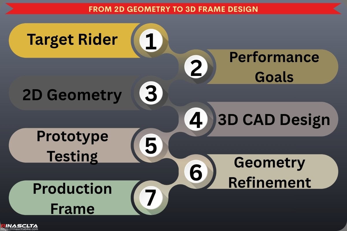
- Geometry chart development: Engineers define the complete geometry chart, including stack, reach, head tube angle, seat tube angle, wheelbase, chainstay length, BB drop, fork rake, trail, front-center, standover height, and size grading, so the frame has clear fit, handling, and performance targets across all sizes.
- 3D CAD validation: The 2D geometry is converted into a full 3D frameset model with tube shapes, junction transitions, aerodynamic profiles, internal cable routing, BB structure, head tube design, dropout interfaces, brake mounts, and seatpost system, allowing the manufacturer to evaluate structure, manufacturability, and mold feasibility.
- Clearance and compatibility verification: The 3D model is checked against real component standards such as wheel size, tire clearance, crankset clearance, chainring space, brake caliper position, rotor clearance, headset system, bottom bracket type, thru-axle standard, derailleur hanger, cockpit routing, and bottle cage position to prevent assembly interference before mold development.
- Prototype evaluation: A 3D printed sample or first carbon prototype is used to confirm visual proportion, component fit, cable routing, tire clearance, rider position, assembly process, and early ride-feedback direction, reducing mold-revision risk and improving production readiness before moving toward final tooling and mass production.
Geometry chart development
Geometry chart development is the 2D foundation stage where the frame’s complete dimensional system is defined before 3D CAD, mold design, carbon layup engineering, and prototype production begin. From a professional carbon bike manufacturer’s perspective, the geometry chart is not only a size table; it is the technical blueprint that controls rider fit, handling behavior, weight distribution, tire clearance, component compatibility, frame size scaling, and category-specific ride feel.
At this stage, engineers define key dimensions such as stack, reach, head tube angle, seat tube angle, effective top tube, wheelbase, chainstay length, bottom bracket drop, fork rake, trail, front-center, standover height, seat tube length, head tube length, fork length, and maximum tire clearance. These values must match the target rider and intended use, whether the frame is designed for aero road racing, endurance riding, gravel, bikepacking, MTB, or e-bike applications.
A professional geometry chart also needs to consider frame size progression, meaning each size should maintain consistent fit and handling rather than simply scaling larger or smaller. For example, smaller sizes may need careful control of toe overlap, standover height, front-center, and stack, while larger sizes may require attention to wheelbase, torsional stiffness, rider weight distribution, and cockpit length. Good 2D geometry development improves fit accuracy, ride confidence, design efficiency, CAD accuracy, prototype success rate, and production readiness, while poor geometry planning can lead to unstable handling, poor rider fit, component interference, expensive redesigns, and mold modification later in the project.
3D CAD validation
3D CAD validation is the stage where the approved 2D geometry is transformed into a real engineering model that can be manufactured, assembled, tested, and eventually mass-produced. From a professional carbon bike manufacturer’s perspective, this is where theoretical dimensions become an actual frame structure, allowing engineers to verify whether the geometry works in combination with tube shapes, carbon construction requirements, component standards, manufacturing limitations, and performance objectives.
During this stage, engineers create the complete 3D frameset, including the head tube, down tube, top tube, seat tube, bottom bracket shell, chainstays, seatstays, dropouts, fork, cable-routing channels, bearing seats, brake mounts, bottle cage locations, storage systems, and seatpost interfaces. The model is then evaluated for factors such as tube-to-tube junction transitions, wall thickness distribution, carbon layup space, mold split feasibility, EPS core design, structural load paths, aerodynamic integration, and overall manufacturability. Unlike a 2D geometry drawing, the 3D model reveals real-world engineering challenges that may not be visible during the geometry stage.
3D CAD validation also allows manufacturers to perform detailed engineering reviews before investing in tooling, helping verify assembly feasibility, stiffness targets, weight objectives, rider positioning, tire clearance, fork compatibility, drivetrain integration, and production tolerances. By identifying potential issues early, manufacturers can reduce the risk of mold modifications, prototype failures, assembly conflicts, and development delays. As a result, strong 3D CAD validation improves engineering accuracy, manufacturing efficiency, prototype success rates, tooling reliability, and overall product quality, making it one of the most important steps in modern carbon bike frame development.
Clearance and compatibility verification
Clearance and compatibility verification is the engineering process of confirming that all major components can function together within the frame without interference before mold development and prototype production begin. From a professional carbon bike manufacturer’s perspective, this stage is critical because a frame may look correct in geometry drawings yet still fail to accommodate real-world components, assembly requirements, manufacturing tolerances, or future industry standards. Using the 3D CAD model, engineers verify every critical interface to ensure the frame is compatible with its intended components while maintaining safety, durability, serviceability, and performance.
Tire clearance verification confirms that the frame and fork provide sufficient space around the tire under all riding conditions. Engineers evaluate not only the nominal tire size, such as 700×32C, 700×45C, 700×50C, 29×2.4”, or 27.5×2.6”, but also account for wheel flex, mud accumulation, manufacturing tolerance, and tire brand variation. Proper tire clearance improves rider safety, mud shedding, off-road capability, comfort, and future compatibility.
Drivetrain compatibility verification ensures that cranksets, chainrings, cassettes, chains, front derailleurs (if applicable), rear derailleurs, and bottom bracket systems function without interference. Engineers evaluate factors such as chainline, chainring clearance, crank-arm clearance, rear tire spacing, dropout position, UDH compatibility, transmission systems, BB standard, and cassette capacity to guarantee smooth shifting, drivetrain efficiency, and long-term reliability.
Fork compatibility verification ensures the frame works correctly with the intended fork specification, including fork length, fork offset (rake), steerer dimensions, crown clearance, headset standard, brake mount location, axle standard, and tire capacity. Because fork dimensions directly influence trail, steering response, wheelbase, front-center length, and handling behavior, even small deviations can significantly affect ride characteristics. Proper verification ensures that the final production frame delivers the intended fit, handling, stability, and performance established during geometry development.
Prototype evaluation
Prototype evaluation before mold creation is the pre-tooling verification stage where the 3D frame design is reviewed through 3D printed samples, CNC mockups, virtual assembly checks, component fit testing, and visual proportion assessment before investing in expensive production molds. From a professional carbon bike manufacturer’s perspective, this stage does not test final carbon strength, but it confirms whether the frame shape, geometry, tube transitions, tire clearance, fork fit, cockpit integration, cable routing, bottle cage position, seatpost system, dropout design, brake mount location, and overall assembly logic are correct in real physical space. Good prototype evaluation helps identify issues such as component interference, awkward cable routing, insufficient clearance, poor tube shaping, difficult assembly, styling imbalance, or rider-position concerns early, reducing mold-revision risk, shortening development time, improving communication between client and engineering team, and ensuring the final carbon mold is built from a design that is already validated for fit, function, appearance, and production feasibility.
Common Geometry Design Challenges
Common geometry design challenges usually come from balancing rider fit, handling behavior, frame size coverage, ride consistency, and modern component integration within one production-ready carbon frame platform. A geometry that fits well may not always handle correctly, and a frame that feels stable in one size may become too nervous, too long, or too flexible in another size if stack, reach, wheelbase, trail, front-center, chainstay length, fork offset, and carbon layup scaling are not carefully managed. Modern manufacturers must also design around evolving standards such as wider tires, integrated cockpits, hidden cable routing, disc brakes, UDH systems, larger cassettes, electronic shifting, and bikepacking mounts, making geometry development a complex engineering process that must balance performance, compatibility, manufacturability, and consistent ride feel across the full size range.
Balancing fit and handling
Balancing fit and handling is one of the most difficult challenges in bicycle geometry design because the dimensions that improve rider fit often influence handling behavior at the same time. From a professional carbon bike manufacturer’s perspective, geometry is not simply about making the rider comfortable; it must also ensure proper weight distribution, steering response, cornering stability, front-wheel traction, rear-wheel traction, climbing behavior, and high-speed control. A bike that fits perfectly on paper can still feel unstable, sluggish, nervous, or difficult to control if the rider’s position is not properly integrated into the overall handling design.
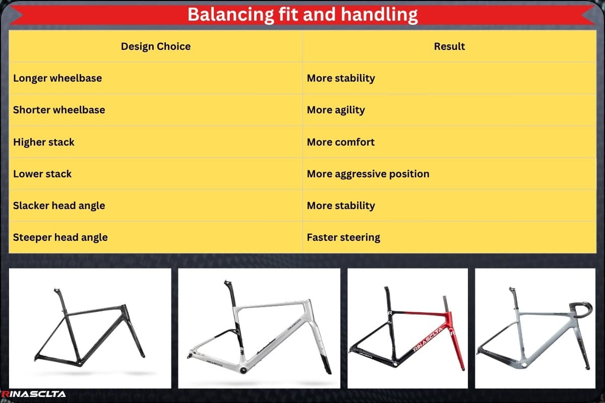
The challenge comes from the fact that changing one dimension often affects several others. Increasing stack may improve comfort but can shift rider weight rearward and reduce front-wheel loading. Extending reach may create a more aerodynamic position but can increase rider fatigue or make steering feel less natural. A shorter front-center may improve responsiveness but increase toe overlap risk, while a longer wheelbase may improve stability but reduce agility. Engineers must therefore balance stack, reach, wheelbase, trail, chainstay length, head tube angle, seat tube angle, and rider center of gravity as a complete system rather than optimizing any single measurement.
Professional manufacturers solve this challenge by first defining the target rider profile, intended use case, flexibility level, riding duration, terrain type, and performance objectives before developing geometry. Rather than pursuing the lowest stack, longest reach, or most aggressive handling possible, engineers establish a fit window that allows the rider to maintain efficient posture while preserving the desired handling characteristics. This process is validated through geometry simulation, 3D CAD reviews, rider fit analysis, prototype testing, and real-world ride feedback to ensure that comfort, efficiency, stability, and responsiveness remain balanced.
When executed correctly, balancing fit and handling creates a bike that feels natural and intuitive from the first ride. The rider can maintain power efficiently, remain comfortable over long distances, and confidently control the bike in corners, descents, and technical situations. This is why experienced manufacturers view geometry not as a collection of numbers, but as the process of optimizing the relationship between the rider, the bicycle, and the intended riding environment.
Accommodating multiple frame sizes
Accommodating multiple frame sizes is one of the most complex challenges in bicycle geometry development because riders of different heights do not simply need a larger or smaller version of the same frame. From a professional carbon bike manufacturer’s perspective, each size must provide similar fit quality, handling behavior, weight distribution, stiffness characteristics, and riding experience, despite significant differences in rider body proportions, weight, center of gravity, and component dimensions. A geometry that works perfectly in a medium size may perform very differently when scaled directly into an extra-small or extra-large frame.
The challenge arises because frame scaling affects much more than seat tube and top tube length. As sizes change, engineers must manage stack, reach, wheelbase, front-center, head tube length, seat tube angle, chainstay length, trail, standover height, toe overlap, tire clearance, and component fit simultaneously. Smaller frames often face issues such as toe overlap, limited bottle cage space, shorter head tubes, and restricted tire clearance, while larger frames can experience excessive wheelbase growth, increased frame flex, longer steering response, and altered rider weight distribution. Simply scaling every dimension proportionally can create bikes that fit differently and handle inconsistently across the size range.
Professional manufacturers address this challenge through size-specific geometry development and frame size grading rather than simple proportional scaling. Engineers may adjust head tube angle, fork offset, seat tube angle, chainstay length, front-center distance, and stack-to-reach ratio independently for different sizes to maintain similar handling characteristics and rider positioning. Modern development also uses 3D CAD validation, rider fit databases, prototype testing, and handling simulations to evaluate how each size behaves under real riding conditions.
When executed correctly, a rider on an XS frame and a rider on an XL frame should experience a similar balance of comfort, steering response, stability, climbing behavior, cornering confidence, and overall ride character. This consistency is one of the hallmarks of professional geometry engineering and is a key reason why high-end manufacturers invest significant time in size-specific development rather than treating geometry scaling as a simple mathematical exercise.
Maintaining consistent ride characteristics across sizes
Maintaining consistent ride characteristics across sizes is one of the most advanced challenges in geometry engineering because riders expect an XS frame and an XL frame to deliver the same handling philosophy, fit intent, and riding experience, even though the frames differ significantly in dimensions, rider weight, leverage forces, and structural requirements. From a professional carbon bike manufacturer’s perspective, geometry development is successful only when every size in the range preserves the intended balance of stability, responsiveness, cornering behavior, climbing efficiency, descending confidence, and rider positioning rather than simply matching a set of geometry numbers.
The challenge exists because handling characteristics are influenced by many interconnected factors. As frame size increases or decreases, values such as front-center length, wheelbase, trail, stack, reach, rider center of gravity, weight distribution, steering leverage, and frame stiffness naturally change. A smaller frame may become too quick and nervous if trail is not controlled properly, while a larger frame may feel slow or sluggish if wheelbase and steering geometry grow excessively. At the same time, rider body proportions change across sizes, meaning the position of the rider’s mass relative to the wheels also changes, further affecting handling.
Another challenge comes from the structural side of carbon frame development. Larger frames experience greater bending loads and longer tube spans, while smaller frames often have tighter packaging constraints and shorter load paths. If engineers use identical tube shapes and carbon layup schedules across all sizes, the ride feel can vary significantly, with larger frames feeling less responsive and smaller frames feeling overly rigid. This is why premium manufacturers increasingly use size-specific carbon layup tuning, reinforcement strategies, and stiffness targets in addition to geometry adjustments.
Professional manufacturers solve this problem through size-specific geometry development, handling simulations, rider-fit analysis, prototype testing, and size-dependent engineering refinement. Instead of scaling every dimension proportionally, engineers carefully adjust parameters such as head tube angle, fork offset, trail, seat tube angle, chainstay length, front-center distance, and carbon layup schedules to maintain consistent steering behavior and rider balance throughout the size range. The objective is that whether a rider chooses an XS, M, or XL frame, they experience the same design philosophy, the same handling confidence, and the same intended performance characteristics, creating a cohesive product platform rather than a collection of unrelated frame sizes.
Integrating modern component standards
Integrating modern component standards is challenging because frame geometry no longer only needs to define rider fit and handling; it must also create enough space and correct interfaces for today’s wider tires, disc brakes, thru-axles, internal cable routing, integrated cockpits, electronic shifting, UDH systems, larger cassettes, wider chainlines, aero seatposts, frame storage, and bikepacking mounts. From a professional carbon bike manufacturer’s perspective, every component standard affects geometry, structure, mold design, carbon layup, tolerance control, and assembly reliability, so compatibility must be planned before 3D CAD validation and mold development.
The difficulty is that many modern standards compete for the same physical space inside the frame. Wider tires require more clearance around the chainstays, seatstays, fork crown, and seat tube; larger chainrings and wider cassettes affect chainline and drivetrain clearance; internal routing requires enough tube volume and smooth cable paths; integrated cockpits change headset structure and steering layout; disc brakes create local load requirements around the fork and rear triangle; and UDH or transmission-style systems require precise dropout geometry and hanger interface control. If these details are not solved early, the frame may pass basic geometry review but fail during assembly with problems such as tire rub, brake rub, cable friction, poor shifting, limited steering angle, bearing interference, weak insert positioning, or expensive mold revisions.
A professional way to manage this is to define a complete component compatibility package before final geometry release, including maximum tire size, rim width, axle standard, brake mount type, rotor size, headset system, bottom bracket standard, drivetrain type, chainring clearance, cable-routing method, seatpost system, hanger standard, bottle cage position, storage design, and accessory mounts. Engineers then validate these requirements in 3D CAD using real component envelopes, tolerance allowances, steering-angle checks, tire-growth margins, mud-clearance rules, and assembly simulations. This ensures the final production frame is not only geometrically correct, but also compatible, serviceable, manufacturable, and reliable for real-world riders.
How OEM/ODM Manufacturers Develop Custom Geometry?
Custom geometry development in OEM/ODM projects is a structured engineering process that transforms a brand’s rider requirements, performance goals, and market positioning into a unique frame platform. Depending on the project scope, manufacturers may begin by modifying an existing geometry platform to reduce development time and cost, or develop an entirely new geometry from scratch when specific fit, handling, or performance targets cannot be achieved through existing designs. Throughout the process, geometry decisions are validated through engineering analysis, rider testing, real-world feedback, and multiple refinement cycles, ensuring that rider fit, steering behavior, stability, comfort, component compatibility, and production feasibility are optimized before mold investment. This iterative approach allows manufacturers to minimize development risk while creating a geometry platform that accurately reflects the intended riding experience and brand identity.
Using existing platforms
Using existing platforms is the typical ODM geometry development approach, where the manufacturer starts from a proven carbon frame design with existing geometry data, 3D CAD files, molds, layup schedules, testing records, component standards, and production QC procedures already in place. This allows brands to shorten development time, reduce mold investment, lower engineering risk, and enter the market faster while still customizing key commercial elements such as paint design, logo placement, component specification, tire setup, cockpit system, packaging, and sometimes minor geometry or layup options. From a professional manufacturer’s perspective, the value of an existing platform is that its fit logic, handling behavior, fatigue performance, assembly compatibility, tire clearance, BB/headset/dropout standards, and production repeatability have already been validated, making it a practical choice for brands that want reliable road, gravel, endurance, aero, or MTB products without building a completely new frame from zero.
Developing new geometry from scratch
Developing new geometry from scratch is the typical OEM geometry development approach, where the manufacturer creates a completely new frame geometry based on the brand’s target rider, riding category, performance goals, fit philosophy, and market positioning instead of starting from an existing platform. This process begins with defining stack, reach, wheelbase, head tube angle, seat tube angle, chainstay length, bottom bracket drop, fork rake, trail, front-center, standover height, tire clearance, size grading, and component standards, then converting these requirements into a new 2D geometry chart, 3D CAD frame model, prototype sample, mold design, and final production specification.
The value of this approach is full control. A brand can create a unique riding personality for aero road, endurance, gravel, MTB, e-bike, bikepacking, or all-road applications, with geometry tuned for specific goals such as aggressive race fit, long-distance comfort, gravel stability, technical control, load-carrying confidence, or aerodynamic efficiency. Compared with ODM, OEM geometry development requires more time, testing, and tooling investment, but it gives the brand stronger product differentiation, proprietary design ownership, exclusive mold control, fit strategy, handling identity, and long-term platform value.
Rider testing and feedback
Rider testing and feedback are used to verify whether the custom geometry delivers the intended fit, handling, stability, comfort, responsiveness, control, and rider confidence in real riding conditions. From a professional carbon bike manufacturer’s perspective, CAD data and geometry charts can define the design direction, but only test riders can confirm how the bike actually feels during acceleration, climbing, sprinting, cornering, descending, braking, rough-road riding, gravel control, or loaded bikepacking use. Feedback on stack and reach comfort, steering speed, front-wheel grip, rear-wheel traction, wheelbase stability, BB drop behavior, trail feel, cockpit position, and fatigue over distance helps engineers decide whether the geometry matches the target rider and intended use. This stage adds value because it converts geometry from theoretical numbers into validated ride performance, reducing redesign risk before mold finalization and improving the final frame’s market fit, ride quality, product confidence, and long-term customer satisfaction.
Iterative refinement before tooling
Iterative refinement before tooling is the controlled adjustment stage where the manufacturer reviews 2D geometry, 3D CAD structure, rider feedback, component clearance, handling targets, size grading, and production feasibility before committing to expensive mold development. This step may involve small changes to stack, reach, head tube angle, fork rake, trail, wheelbase, chainstay length, BB drop, tire clearance, dropout position, cable routing, cockpit layout, and frame size progression to improve fit, stability, responsiveness, comfort, assembly compatibility, and manufacturability. From a professional carbon bike manufacturer’s perspective, this stage is valuable because modifying geometry in CAD is far cheaper and faster than changing a finished mold; good pre-tooling refinement reduces mold revision risk, prototype failure, component interference, unstable handling, poor size consistency, production delays, and unnecessary development cost, while helping ensure the final tooling is built from a geometry platform that is already validated for real-world riding and mass production.
Future Trends in Bike Geometry Development
Future bike geometry development is increasingly focused on creating bicycles that are faster, more versatile, more comfortable, and better adapted to real-world riding conditions rather than pursuing extreme race-specific characteristics. As component technology, rider expectations, and performance data continue to evolve, geometry engineering is becoming more integrated with tire technology, cockpit systems, rider-fit analytics, aerodynamic optimization, and digital performance analysis.
Larger tire clearances are becoming a major influence on geometry design as riders increasingly favor wider tires for improved comfort, traction, rolling efficiency, and surface versatility. Modern road bikes that once targeted 25 mm tires are now commonly designed around 30–35 mm clearance, while gravel bikes continue moving toward 45–55 mm tire capacity and 32 inch grave bike with 32 inch wheels are getting into the market since 2026 Unbound Gravel event. This trend affects chainstay length, fork design, wheelbase, BB drop, seat tube shaping, and front-center dimensions, requiring geometry to balance stability, aerodynamics, and tire compatibility.
Integrated cockpits are also changing geometry development. Fully integrated handlebars, stems, headset systems, and cable routing create cleaner aerodynamics and improved aesthetics but reduce traditional fit adjustability. As a result, manufacturers must place greater emphasis on stack, reach, frame sizing strategy, stem integration, spacer systems, and rider-position accuracy during the early stages of geometry development to ensure proper fit without relying on extensive aftermarket adjustments.
Endurance-performance hybrids represent one of the fastest-growing geometry categories. Rather than separating race bikes and endurance bikes into completely different segments, many modern platforms now combine the efficiency and responsiveness of race geometry with the comfort and stability traditionally associated with endurance designs. This approach often uses moderate reach values, optimized stack heights, wider tire compatibility, balanced trail figures, and longer-distance rider positioning, creating bikes that perform well across a broader range of riding conditions.
Data-driven geometry development is likely to become one of the most significant future trends. Manufacturers increasingly use bike-fitting databases, rider biometrics, pressure mapping, GPS ride analysis, motion-capture systems, power data, simulation software, and real-world testing feedback to refine geometry decisions. Rather than relying solely on historical design practices, future geometry platforms will be developed using measurable rider-performance data, allowing engineers to optimize fit consistency, handling behavior, rider efficiency, comfort, and performance outcomes with greater precision than ever before.
Conclusion
Geometry is one of the most important decisions in bicycle development because it defines how the rider interacts with the bike and how the bike performs in real-world conditions. Long before carbon layup, tube shaping, or component selection can influence ride quality, geometry establishes the foundation for rider fit, handling behavior, stability, comfort, efficiency, control, and overall riding experience. Well-executed geometry development aligns the frame with its intended rider, use case, and performance objectives while ensuring compatibility with modern component standards and future market demands. For OEM and ODM projects alike, investing in proper geometry engineering helps create products that not only ride better but also achieve stronger market differentiation, improved customer satisfaction, and greater long-term commercial success.